
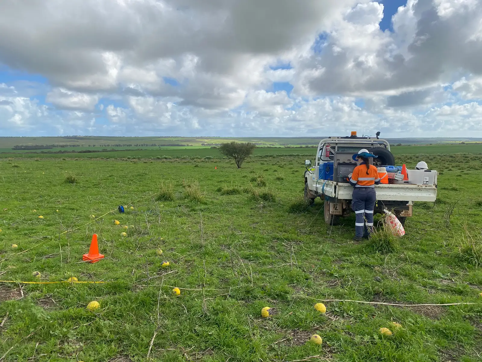
Soil and thermal resistivity testing
We provide soil resistivity testing using the standard Wenner 4-electrode method to measure earth resistance for electrical grounding applications. Our in-situ thermal resistivity testing provides data to support the design of underground power cable networks, geothermal wells and pipeline infrastructure.
Soil Resistivity Testing is routinely used to measure earth impedance or resistance for electrical grounding circuits. The Wenner 4-electrode test is the standard configuration for Soil Resistivity Testing and a-spacing of electrode separation is dependent on Client grounding specifications. Each test location has orthogonal tests (or soundings) and the measured apparent resistivity (ρ) and a-spacing (m) are plotted against one another at a log-scale to produce a 1D curve. An example field set-up is shown in Figure 1, and an example output of a Soil Resistivity Testing result is illustrated in Figure 2.
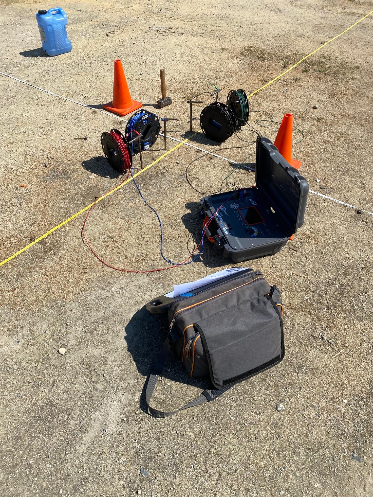
Figure 1. Example image of a soil resistivity (4-electrode Wenner method) field set-up (image source. Draig Geoscience).
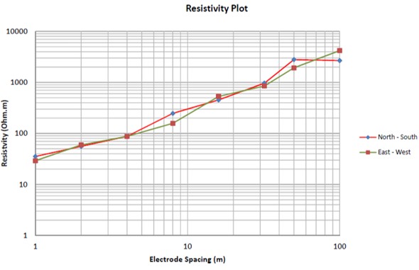
Figure 2. Example image of a soil resistivity (Wenner 4-electrode method) result (note. axis in log-scale) (image source. Draig Geoscience).
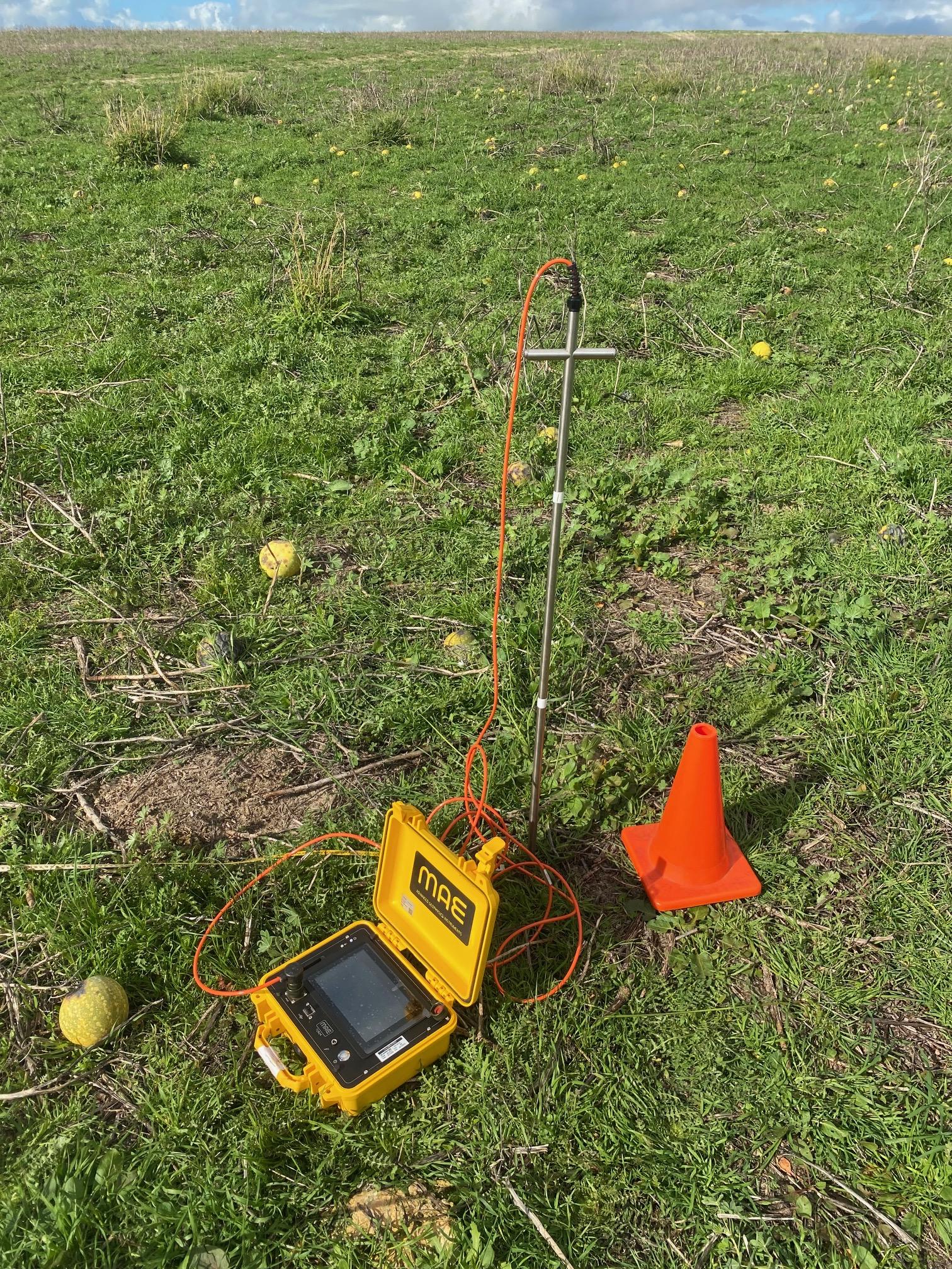
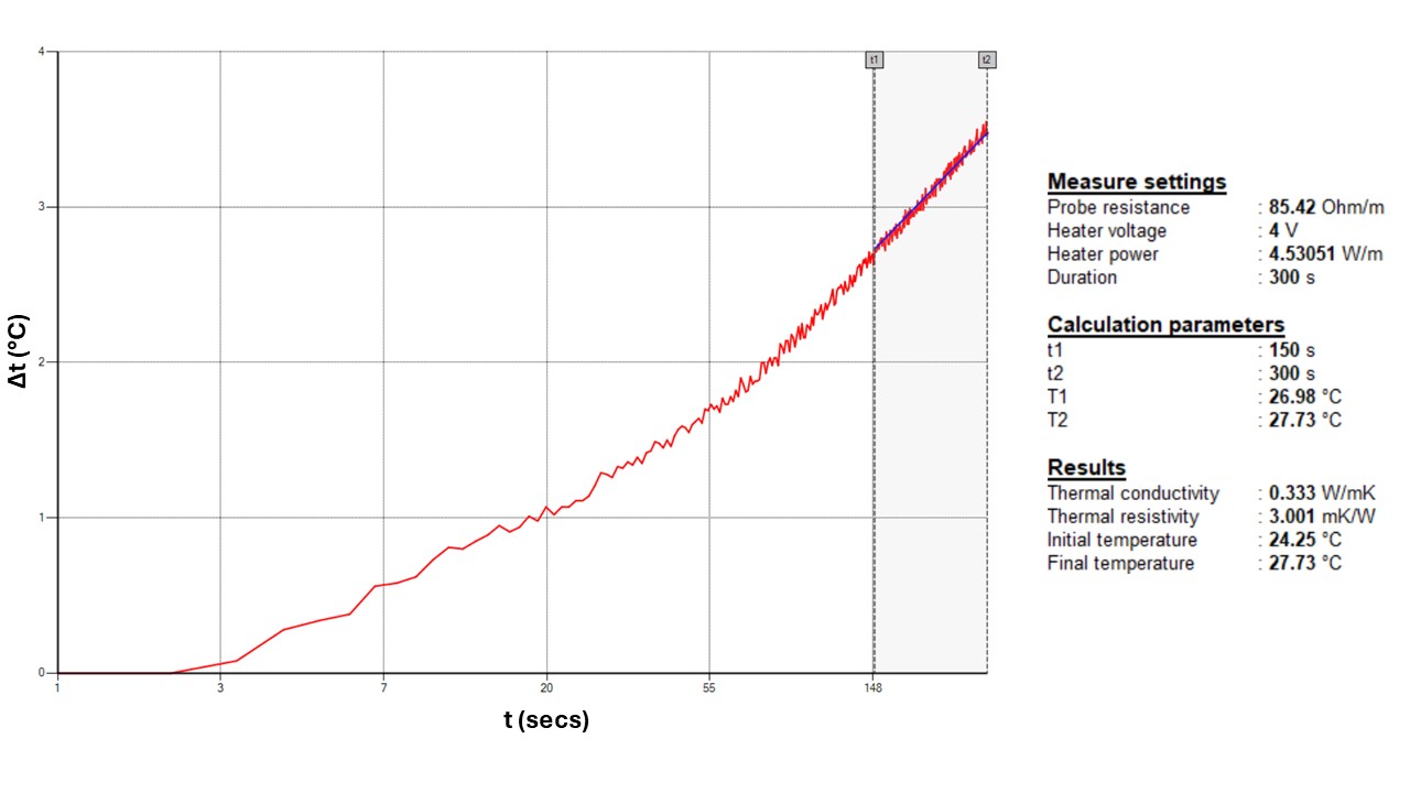
Thermal Resistivity testing is an in-situ method for quantifying native soil and rock thermal resistivity. These measurements are advised to be accompanied by soil moisture measurements at the same sample depth. The thermal resistivity results are most useful as input criteria in underground power cable networks, geothermal wells, and pipeline infrastructures design. An example field set-up is shown in Figure 1, and an example output of a Thermal Resistivity Testing result is illustrated in Figure 2.
Find the right solution for your next geoscience project
Talk to our experienced consultants about your project requirements. We help you discover the right approach for understanding subsurface conditions.