
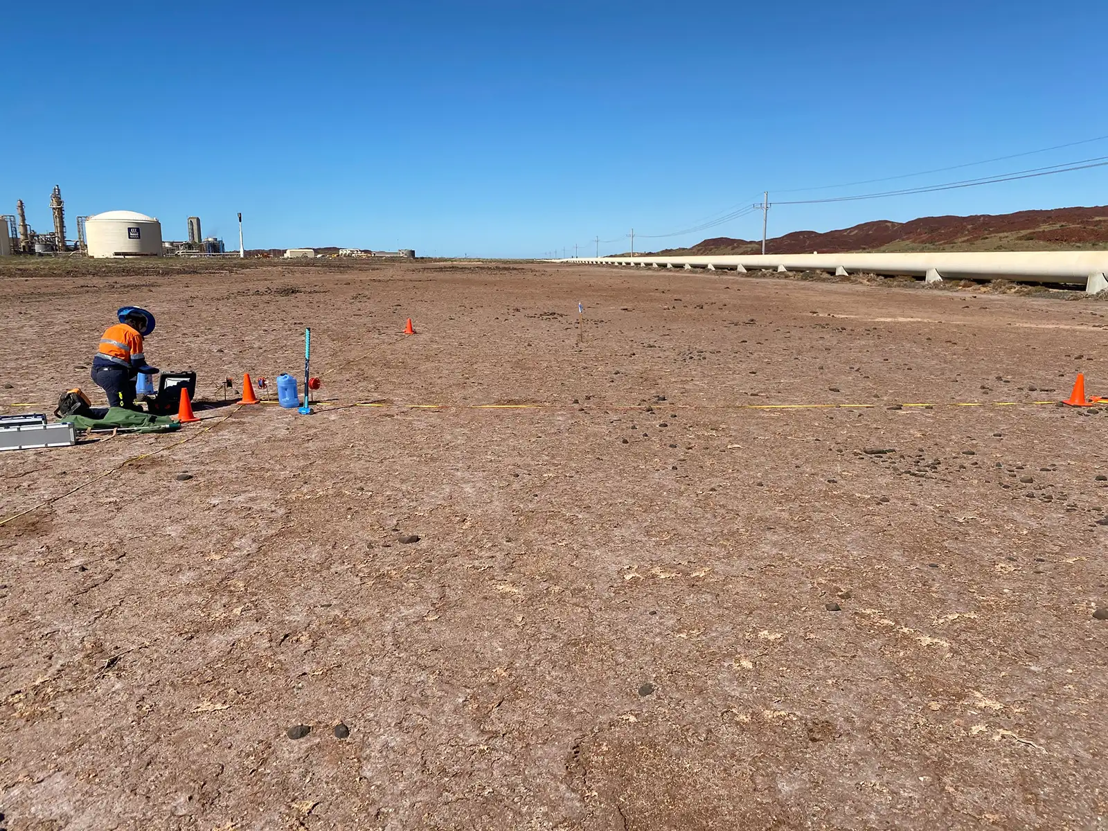
Groundwater mapping
Groundwater is becoming an increasingly critical resource across Australia and geophysical technologies can be used to measure depth to groundwater, as well as fresh/saline interfaces and changes in the salinity.
Aquifers, containing water flows, and aquitard materials, containing trapped water, provide ideal geological conditions to delineate layers and confining units using electrical and electromagnetic techniques. These techniques are highly dependent on porosity and water content of the subsurface geology.
Electrical Resistivity Imaging (ERI) maps the differences in the electrical properties of the subsurface if an electrical resistivity contrast exists between materials. The ERI technique is highly dependent on the porosity and water content of the earth material e.g. the greater the water content the larger the electrical conductivity. For example, an accurate gradiential boundary may be observed where a strong electrical contrast exists between a highly porous, low resistivity, water-filled aquifer regions and a less porous, less saturated, higher resistivity surrounding geology. Aquitards also generally act as electrical conductors as they often consist of water-trapped geological materials such as clay, calcrete etc. These geological materials generally allow for an easier flow of electrical current.
Electromagnetic (EM) methods act in a similar way to electrical methods e.g. ERI, as electrical conductivity is the inverse of electrical resistivity. Where a large electrical contrast is present in the geological materials due to the porosity or water content of the geology, a gradiential change should be observed. For example, an accurate gradiential boundary may be observed where a strong electrical contrast exists between a highly porous, high conductive, water-filled aquifer regions and a less porous, less saturated, lower conductivity surrounding geology. Aquitards also generally act as electrical conductors as they often consist of water-trapped geological materials such as clay, calcrete etc. These geological materials generally allow for an easier flow of electrical current.
Geological fracture and fault zones may influence local and regional groundwater passages and flows, which makes these important hydrogeological features to understand and locate. The geological material surrounding the fault contact, may generally be more porous and contain a higher water content than the denser, less porous basement material either side of the fault. This type of geological setting is well suited for electrical and electromagnetic geophysical methods. The geological material surrounding the fault contact, may generally be more fractured and contain material of a different type to that either side of the fault. This type of geological setting is also well suited for seismic and potential field (gravity and magnetic) methods.
Seismic Reflection is a geophysical technology which is directly related to the acoustic impedance between geological materials; the greater the acoustic impedance the greater seismic reflection. This technology is most useful where the density contrast/acoustic impedance between geological materials is large, such as in and around fault contact zones. These fault features can be observed as high amplitude seismic reflection amplitude responses or as offsets in seismic reflection layers.
Electrical Resistivity Imaging (ERI) maps the differences in the electrical properties of the subsurface if an electrical resistivity contrast exists between materials. The ERI technique is highly dependent on the porosity and water content of the earth material e.g. the greater the water content the larger the electrical conductivity. Fault zones and fracture zones may contain increased hydraulic action or contain weathered/fault-gauge type material such as clays or other similarly conductive geological material. Therefore, an accurate gradiential boundary may be observed where a strong electrical contrast exists between a highly porous, low resistivity, fault contact/fracture region and a less porous, less saturated, higher resistivity basement geology.
Electromagnetic (EM) methods are quick and effective at highlighting regions of faulting. These methods are generally more time-efficient to deploy in a field environment, but provide a broader electrical response in comparison to the ERI method. The physical material properties that effect the measured responses of the EM methods are similar to that of the Electrical methods at fracture and fault contact zones e.g. the greater the water content the larger the electrical conductivity. EM methods are often used as broader mapping tool, with ERI providing more detailed information at regions of targeted interest.
Gravity can be an effective technique for detecting faults. This method measures changes in the density of the subsurface. If a fault is present a difference in the measured gravity data may be observed due to a shift in basement material, causing the basement to be higher/lower to the surface either side of the fault. Also, geological material surrounding a fault may be of a different density in comparison to the geological material either side of the fault. If this density contrast Is large enough a feature will be observed in the gravity dataset. Gravity tends to be used as a broader mapping tool complimented by more targeted electrical and EM methods surveys.
Magnetic methods, similar to gravity methods, can be an effective technique for detecting faults. This method measures changes in the magnetic properties of the geological subsurface. If the geology is magnetic in nature, if a fault is present a difference in the measured magnetic field may be observed due to a shift in basement material. Also, geological material surrounding a fault may be of a different magnetic property in comparison to the geological material either side of the fault. If this magnetic contrast Is large enough a feature will be observed in the magnetic dataset. Magnetic methods tend to be used in conjunction with gravity methods, as the gravity method targets contrasts in geological density in and around the fault zones. Both Magnetic and Gravity methods tend to be used as a broader mapping tool for highlighting fault region and complimented by more targeted electrical and EM surveys.
The extent and depth of paleochannels can be interpreted using most geophysical techniques. The strong contrast between the less dense paleochannel overburden material and the denser basement material, makes seismic and gravity methods suitable for paleochannel mapping. Also, the electrical difference between the paleochannel overburden and basement material provides a strong electrical contrast, which also makes GPR, electrical and electromagnetic (EM) methods suitable methods for mapping the depth and extent of paleochannels.
Seismic Refraction can be used to measure the P-wave (Vp) velocity of soil overburden and basement material. The measured Vp can be cross-correlated with borehole data, used to estimate rippability using rippability charts and calculate engineering moduli when combined with Shear-wave velocity information (Vs) (e.g. Poisson’s Ratio).
Seismic Reflection is a geophysical technology which is directly related to the acoustic impedance between geological materials; the greater the acoustic impedance the greater seismic reflection. This technology is most useful where the density contrast between geological materials is large, such as between the overburden paleochannel geological material and basement. When a large acoustic contrast between the overburden and basement is present the extent of the paleochannel feature can be observed in the interpreted seismic layers.
Ground Penetrating Radar (GPR) is a geophysical technology which is directly related to the dielectric contrast between geological materials; the greater the dielectric contrast the greater GPR reflection. This technology is most useful where the dielectric contrast between geological materials is large, such as between the overburden paleochannel geological material and basement. When a large dielectric contrast between the overburden and basement is present the extent of the paleochannel feature can be observed in the interpreted GPR reflection layers.
Electrical Resistivity Imaging (ERI) maps the differences in the electrical properties of the subsurface if an electrical resistivity contrast exists between materials. The ERI technique is highly dependent on the porosity and water content of the earth material e.g. the greater the water content the larger the electrical conductivity. A paleochannel may contain overburden material which is highly porous and contains a higher water content in comparison to the less porous basement material. An accurate gradiential boundary for the base of the paleochannel may be observed where a strong electrical contrast exists between a highly porous, low resistivity, paleochannel regions and a less porous, less saturated, higher resistivity basement geology.
Electromagnetic (EM) methods are quick and effective at highlighting paleochannel regions. The paleochannel geological material may generally be more porous and contain a higher water content than the denser, less porous basement material. Where a strong electrical contrast exists between the higher electrically conductive paleochannel overburden and lower electrically conductive basement material, the general depth and extent of the paleochannel may be mapped.
Gravity can be an effective technique for detecting paleochannels. This method measures changes in the density of the subsurface. If a paleochannel is present a difference in the measured gravity data may be observed due to a deepening of the basement material in the paleochannel region.
Contamination plumes, salt-water intrusions and fresh water-saline interfaces can be delineated using electrical and electromagnetic (EM) methods. These techniques are highly dependent on porosity and water content of the subsurface geology, but are also highly influenced by the salt/mineral content of groundwater or geological layers e.g. tailings contamination, salt-water or clays.
Electrical Resistivity Imaging (ERI) also targets regions of conductivity variation associated with contamination plumes or salt-water intrusions. ERI is a preferred methodology for showing the depth extent of a contamination plume/salt-water intrusion along a section profile. By arranging ERI cross-sectional profiles in a parallel orientation, it is possible to periodically map over calendar-time any observable migration of contamination plumes/salt-water zones between profile lines. It is also possible to monitor any changes in dip/strike direction of the migrating groundwater resistivity anomalies.
Electromagnetic (EM) methods are quick and effective at highlighting and monitoring contamination plumes or salt-water intrusions. Depending on depth from surface, extent of the plume/intrusion, closely-spaced parallel EM profiles can laterally constrain electrically high conductive zones often associated with contamination plumes and/or salt-water intrusion. Through repeat surveys over calendar time it is possible to observe and monitor the extension, contraction or migration of plume/intrusion zones.
Find the right solution for your next geoscience project
Talk to our experienced consultants about your project requirements. We help you discover the right approach for understanding subsurface conditions.