
Seismic methods
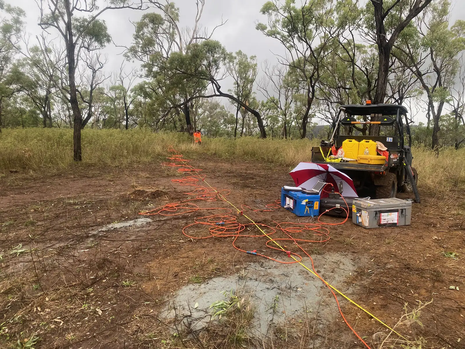
Seismic methods can provide valuable information of the subsurface, such as the seismic velocity structure of the geology (e.g. using seismic refraction, surface-wave methods) and the presence of geological layers due to their seismic reflectivity (e.g. seismic reflection). Large contrasts in the density of the subsurface can be measured, modelled and displayed in a seismic velocity map or cross-section format (P-wave, Shear-wave).
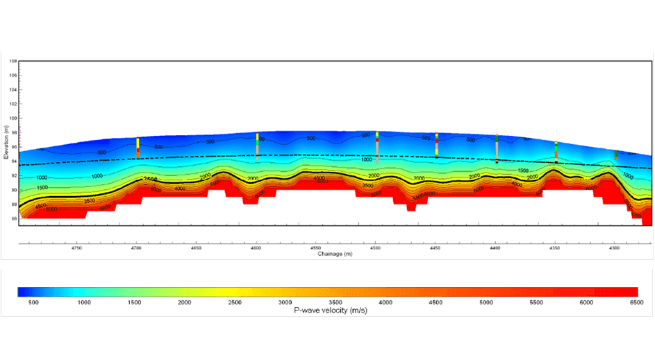
Seismic refraction is a seismic technology that can be used to measure the P-wave velocity, Vp, of the subsurface geology. Vp information can be useful for interpreting depths to bedrock and other geological boundaries. Vp is directly influenced by the elastic modulus of geological material, i.e. the stiffer or more consolidated the geologic material, the larger the value of Vp. Seismic refraction cannot however measure inversions in layer Vp, e.g. stiffer geological layers overlying less stiff geological layers. It is useful in defining the first basement material interface, and this can be used to constrain other layer interpretations with other geophysical technologies e.g. Multichannel Analysis of Surface Waves (MASW). An example of a seismic refraction tomographic cross-section can be viewed in Figure 1.
Note: Seismic Refraction is affected by external seismic noise and is recommended to be utilised in areas of low seismic noise e.g. away from active drill rigs. Low velocity layers (where the velocity decreases with depth) are invisible to seismic refraction and floaters (e.g. isolated boulders in sediments) cannot be detected.
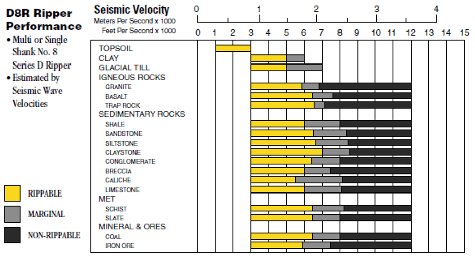
P-wave velocities measured using the seismic refraction method can also be correlated with material rippability e.g. Caterpillar or Komatsu Rippability charts. An example table of correlating P-wave velocity with material rippability is shown in Figure 2.
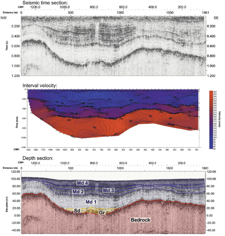
Seismic reflection is a geophysical technology which is directly related to the acoustic impedance between geological materials; the greater the acoustic the greater seismic reflection. This technology is most useful where the density contrast between geological materials is large. Therefore, seismic reflection is useful in defining material interfaces, and this can be used to constrain other layer interpretations with other geophysical technologies e.g. Seismic Refraction or Multichannel Analysis of Surface Waves (MASW). An example of a seismic reflection cross-section correlated with a seismic refraction tomographic cross-section can be viewed in Figure 3.
Note: Seismic reflection is affected by external seismic noise and is recommended to be utilised in areas of low seismic noise e.g. away from active drill rigs. Where a large enough acoustic impedance is not present a reflection may not be visible in the data.
Downhole seismic testing is a downhole geophysical tool with the ability to obtain interval seismic velocity measurements (P-wave, Vp and Shear-wave, Vs).
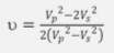
Downhole seismic testing measures the seismic velocity of the geological materials through which acoustic waves travel. Both compressional wave velocity (Vp) and Shear-wave velocity (Vs) at the borehole location can be measured using Downhole seismic testing. The results of the measured velocities are generally plotted against depth to show a 1D curve. Poisson’s Ratio (v) can be calculated using the measured Vp and Vs values through the expression:
With a known density (p) of geological material from the borehole, it can also be possible to calculate the Shear modulus (G) from utilising Vs in the expression:

Note: Downhole seismic testing is affected by external seismic noise and is recommended to be utilised in areas of low seismic noise e.g. away from active drill rigs.
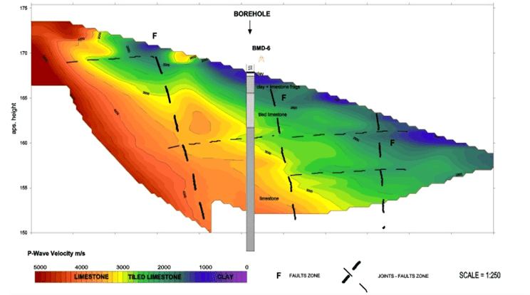
Downhole seismic tomography is a downhole geophysical technology that can image the Vp distribution extending from the borehole. This is a different velocity analysis to the Downhole seismic testing interval velocity method. Shot locations are built-up in a grid around the borehole and if there is a dense enough distribution of shot locations the 2D cross-sections can be combined to produce Vp contour maps at chosen depth intervals. An example output of a 2D Downhole seismic tomography result with borehole data correlation is illustrated in following Figure 1.
Note: Downhole seismic tomography is affected by external seismic noise and is recommended to be utilised in areas of low seismic noise e.g. away from active drill rigs.
Parallel seismic is a downhole geophysical technology that can measure the Vp distribution along a borehole. This is a different velocity analysis to the Downhole seismic testing interval velocity method. A borehole is drilled in parallel with the subsurface structure of interest (e.g. reinforced concrete pile), preferably with a separation no greater than 2 m apart. A seismic shot location is taken at the head (or top) of the pile and the seismic signal generate is measure along the downhole seismic array. An image illustrating a general parallel seismic set-up is shown in Figure 2.
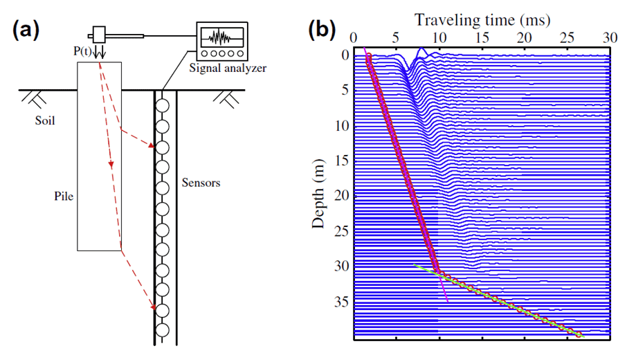
The approximate depth of the pile footing is interpreted as the change in P-wave velocity gradient in the time-depth plot i.e. when the faster P-wave velocity (steeper gradient) travelling through the pile P-wave velocity slows (shallower gradient) travelling through the soils below the pile.
Limitations with this method are similar to other seismic methods i.e. parallel seismic is affected by external seismic noise and is recommended to be utilised in areas of low seismic noise. Changes in seismic velocity are dependent on the density contrast of the sub-surface materials. If materials are of similar elastic and density properties then a change in velocity may not be observed.
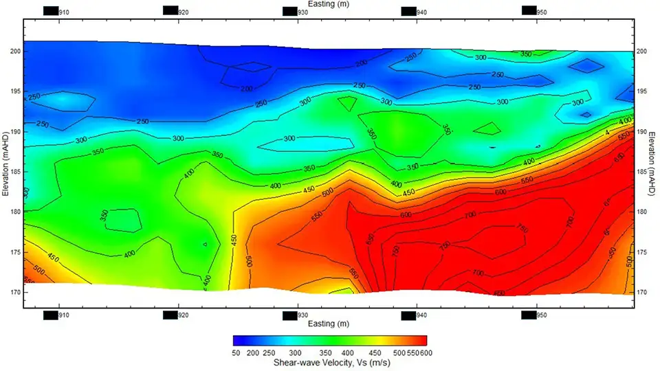
Multichannel Analysis of Surface Waves (MASW) is a surface wave seismic technology which is better suited to a geological setting of interchanging stiff and less stiff geologic layers as this technology can deal with seismic velocity inversions (e.g. a higher velocity layer/stiffer geology, overlying a lower velocity layer/less stiff geology). MASW is a bulk measurement and measures a 1D sounding at a station location over an array of geophones, averaging the shear-wave velocity, Vs, of the ground at the station location. The array can then be moved along a profile line to the next station location. The 1D soundings along the profile line are then used to build-up a 2D Vs cross-section of the profile line.
Why is MASW useful? The calculated Vs can be multiplied with known geological density (ρ) to provide an approximate bulk shear modulus (G) for that geology e.g. G = ρVs^2. Note. MASW is affected by external seismic noise and is recommended to be utilised in areas of low seismic noise. An example of a MASW cross-section can be viewed in Figure 1.
Note: The MASW technique is generally seismic noise resistant, but will be affected by severe background noise caused by e.g. drill rigs, aircraft and earthmoving/excavation machinery. The resolution of the 1D MASW sounding also degrades with depth. As a rule of thumb, the shear wave velocity is averaged over a vertical distance of about half the depth of burial. Surveys must be performed on a flat lying area free of obstructions, dirt piles or ditches; an area of constant gradient or an area where the elevation change between geophones is < geophone spacing.
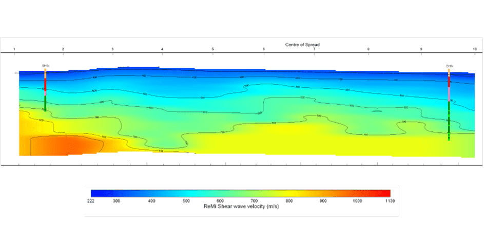
Refraction MicroTremor (ReMi)is a passive surface wave seismic technology(providing Vs) which is also useful in the same geologic settings as MASW. The difference between the two methods is that ReMi records the ambient seismic noise of the geology (not using an active seismic source like MASW e.g. drop weight). Similarly, ReMi can also use an MASW set-up and provides an average of Vs over a deeper depth range. ReMi provides less Vs detail in the near surface to allow for a more general average of Vs at depth.
Why is ReMi useful? The calculated Vs can be multiplied with known geological density(ρ) to provide an approximate bulk shear modulus (K) for that geology e.g. K = ρVs^2. An example of a ReMi cross-section can be viewed in Figure 2.
Find the right solution for your next geoscience project
Talk to our experienced consultants about your project requirements. We help you discover the right approach for understanding subsurface conditions.