
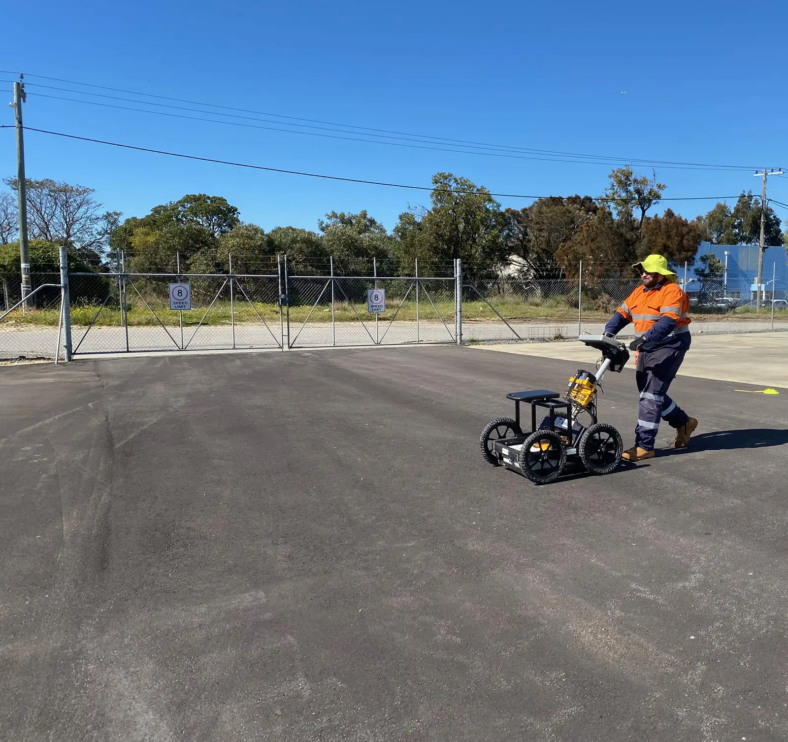
Ground penetrating radar (GPR)
Ground Penetrating Radar (GPR) is a technology that provides a fast, high-resolution image of the subsurface. The propagation of radar waves through a material are highly influenced by the electrical properties of the material and the magnitude of reflection of the radar wave is determined by the dielectric contrast between boundaries within the material under investigation.
Single-channel GPR utilises a single pair of transmitter (Tx) and receivers (Rx) for GPR data acquisition.
Traditionally the acquired GPR data is presented in standard 2D sections (radargrams – see Figure 1), or if multiple GPR profile lines are orientated parallel to each other or in a grid formation, depth-slices of the gridded amplitude reflection data can be presented. Depth-slices are useful for observing if a feature is present across multiple GPR profiles.
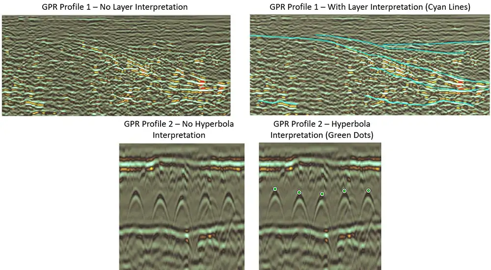
Figure 1. Example images showing single-channel GPR radargrams with and without interpretation features.
General GPR Limitations
– GPR requires a dielectric contrast between the sub-surface target and the surrounding host material in order to observe a reflection at the material interface boundary;
– Strong electrically conductive soils (e.g. clays) or saline groundwater (e.g. salt water) can have strong attenuating effects on the GPR waves limiting (or completely ending) signal penetration.
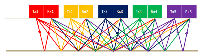
An advantage of Multichannel 3D GPR over conventional single-channel GPR is the area of investigation coverage. A swath of multiple GPR transmitter (Tx) and receiver (Rx) antennas are utilised in Multichannel 3D GPR investigations in comparison to standard GPR investigation which utilise a single channel Tx and Rx antenna. Figure 1 provides an example of potential GPR ray-paths between multiple transmitters and receivers for an example Multichannel 3D GPR set-up.
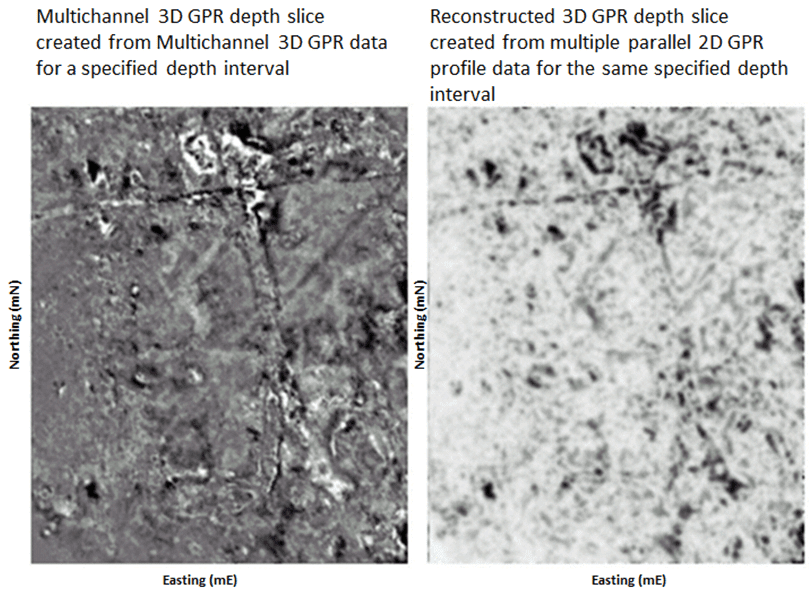
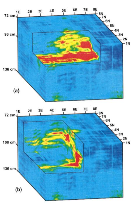
The 3D GPR data results produced from using Multichannel 3D GPR data are of a higher lateral resolution in comparison to reconstructing 3D GPR from multiple parallel 2D GPR profile data (see 3D GPR data comparison for the same depth interval in Figure 2). Note: In both single-channel and multi-channel GPR surveys, the main limitation is that the depth of investigation is influenced in the presence of electrically conductive materials (e.g. clay, saline groundwater).
The GPR method can be utilised to display subtle changes in the sub-surface material of interest over time (time-lapse). Changes in material dielectric contrast can be caused by many factors including material deformation, such as cracking or contamination seepage. 3D regions of interest in the subsurface highlighted by using the GPR method can be monitored over calendar time (4D monitoring) to determine if these regions are propagating, diminishing or showing no signs of change. This information can be particular useful to civil engineers or environmental scientists in reducing the risk of their ground, or infrastructure health monitoring assessments. Examples illustrating the highlighting of internal concrete deformation over time are shown in Figure 1, and the net volumetric changes in a GPR dataset monitoring a dense non-aqueous phase liquid (DNAPL) is shown Figure 2.
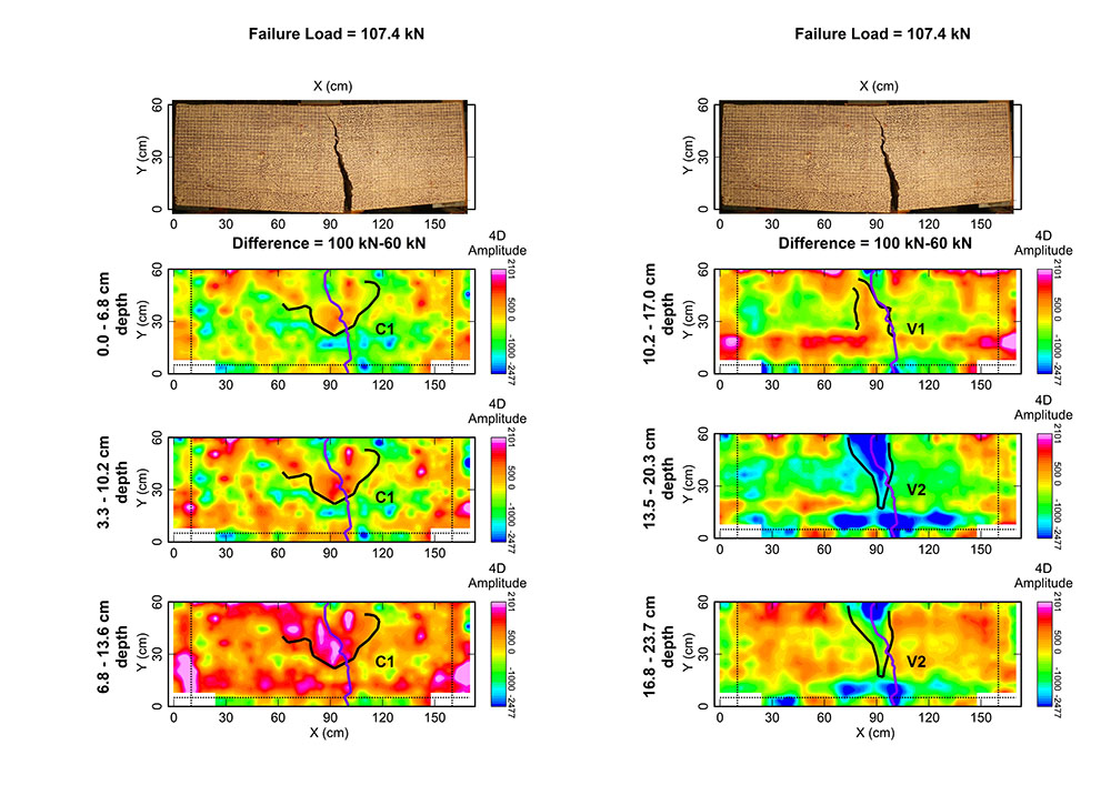
Figure 1. An example of time-lapse GPR amplitude response differences for increasing structural load; final crack location – magenta line. (image source. Tasker, L. et. al (2018). “Time-lapse monitoring of internal alteration of a concrete structure using ground penetrating radar”. Construction and Building Materials, 2018, Vol. 191, p. 300-310)
Find the right solution for your next geoscience project
Talk to our experienced consultants about your project requirements. We help you discover the right approach for understanding subsurface conditions.