
Electrical methods
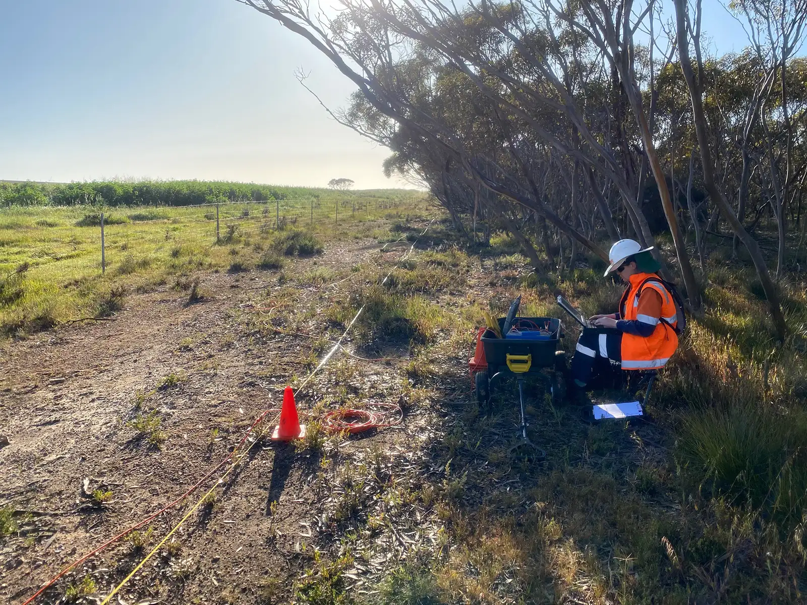
Electrical methods – such as Electrical Resistivity Imaging (ERI), Induced Polarisation (IP), and the 4-electrode Wenner soil resistivity configurations – operate on the principle of injecting a controlled electrical current into the ground and measuring the resulting potential response across the underlying soil and geological formations
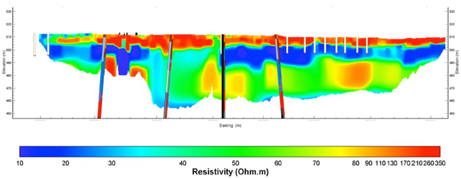
ERI is useful geophysical tool for mapping geologic boundaries, voids and fracture zones, and defining the depth to the water table. Voids and fracture zones that are either clay or air filled are likely to have different electrical properties (resistivity) than the surrounding material. ERI investigates the subsurface immediately below the surveyed line. ERI relies on a contrast in the electrical resistivity of the features being imaged. If there is no resistivity contrast, features will be not be imaged. It will only detect individual localised features (e.g. clay zones) when they have a median dimension exceeding the location of their subsurface depth. An example output of an ERI cross-section with borehole data correlation is illustrated in Figure 1.
Note: ERI can be influenced by cultural EM noise and by surface infrastructure. ERI relies on a contrast in the conductivity of the features being imaged. If there is no conductivity contrast, features will be not be imaged. ERI penetration will be adversely affected by highly conductive materials at or near surface. Survey lines must be in multiples of cable lengths (e.g. 18 m for 1 m electrode spacing). Survey lines must extend approximately 3 times the depth of investigation beyond the area of interest.
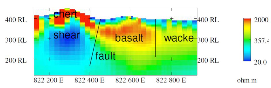
The induced polarisation method (or IP method) is generally suited to exploration investigations, which in general have a greater depth of interest (>80 m depth from surface). In order to achieve larger depth of penetrations, a larger current transmission source is generally required (e.g. a high-power generator) and also larger spacing between receiving potential difference electrodes. The IP method is particularly useful in interpreting electrically conductive geological bodies and fault zones. Figure 1 provides an example cross-section of geologically interpreted IP data.
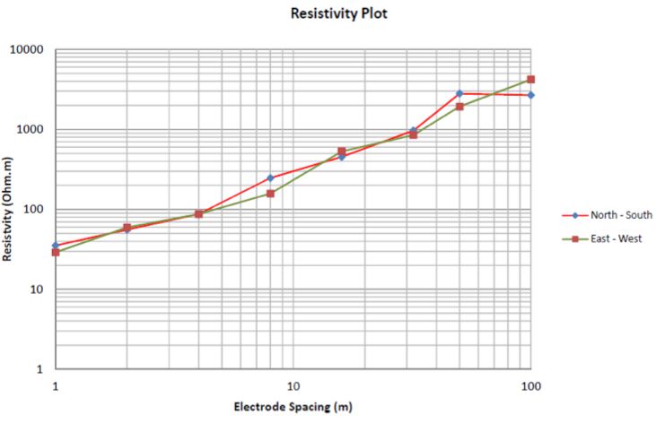
Soil Resistivity Testing is routinely used to measure earth impedance or resistance for electrical grounding circuits. The Wenner 4-electrode test is the standard configuration for Soil Resistivity Testing and a-spacing of electrode separation is dependent on Client grounding specifications. Each test location has orthogonal tests (or soundings) and the measured apparent resistivity (ρ) and a-spacing (m) are plotted against one another at a log-scale to produce a 1D curve. An example output of a Soil Resistivity Testing result is illustrated in Figure 1.
Find the right solution for your next geoscience project
Talk to our experienced consultants about your project requirements. We help you discover the right approach for understanding subsurface conditions.