
Electromagnetics (EM)
A transmitted EM field is generated by a transmitter coil to induce an electrical current in the subsurface. The induced subsurface secondary field, which is created by the induced subsurface electrical current, is detected by the EM receiver. Draig Geoscience offers a range of EM options ranging from Frequency-Domain EM (FDEM), Time-Domain EM (TDEM), to downhole EM and downhole electrical conductivity measurements.
Frequency-Domain Electromagnetic (FDEM) surveying is a fast to deploy, non-destructive method for mapping changes in the ground’s bulk electrical conductivity. It allows us to efficiently scan large areas and visualise what’s beneath the surface without breaking ground.
The FDEM instrument transmits an EM field into the ground, inducing small electrical currents in the subsurface materials. The FDEM system measures the received EM field caused by the Eddy currents and pairs it with GPS tracking to generate detailed 2D contour maps of the site’s bulk conductivity (see Figure 1).
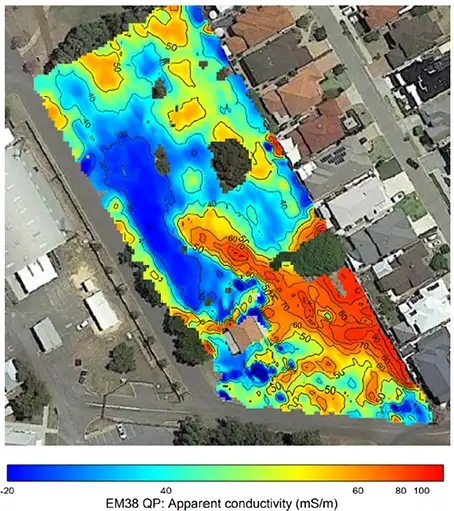
Different materials conduct electricity differently, so this technique is highly sensitive to:
• Soil & groundwater changes (moisture, salt, and clay content)
• Environmental risks (contaminant plumes and landfill boundaries)
• Buried infrastructure (pipes, cables, and underground storage tanks)
FDEM mapping is effective at showing the horizontal location of subsurface features across a site. If your project requires precise depth profiling or centimetre-level vertical accuracy, we can combine FDEM with complementary geophysical methods like Ground Penetrating Radar (GPR) or Electrical Resistivity Imaging (ERI) to give you a more complete understanding of your site.
Time-Domain EM (TDEM) is a useful non-destructive testing tool for mapping sub-surface changes in electrical conductivity. At a specified station, or sounding location, a transmitted EM field is generated by a transmitter coil to induce an electrical eddy current in the subsurface. The induced subsurface secondary field which is created by the induced subsurface electrical current is detected by the EM receiver. The TDEM equipment measures the conductivity value with time at the sounding location. The measured conductivity at the station location can be modelled and with GPS locations of the stations, a 2D cross-section of modelled conductivity can be created. Electrical conductivity is the reciprocal of electrical resistivity, therefore if the units of conductivity (mS/m) are known it is possible to present the same data set in units of electrical resistivity (Ohm.m). An example of a 2D cross-section of modelled resistivity data collected using TDEM is shown in Figure 1.
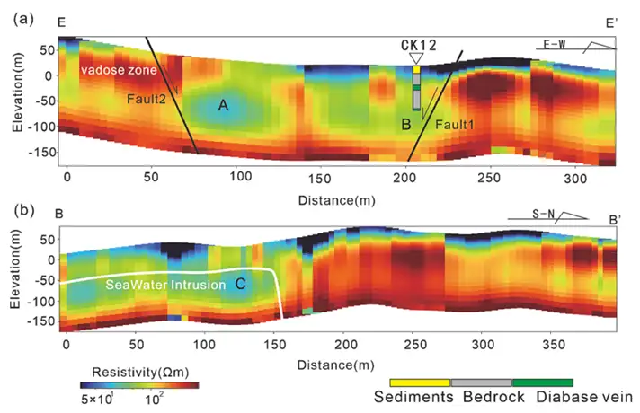
faults in seawater intrusion at Zhoushan islands (Hangzhou Bay, China)’).
Saline groundwater, clay, fresh water and contaminates in the sub-surface can affect the sub-surface apparent electrical conductivity response. This makes TDEM a useful tool to map this type of sub-surface feature. A grid of TDEM stations and/or profile lines make it possible to create contour plan maps of the modelled resistivity/conductivity distribution across the investigation area at specified depth intervals (depth-slice maps).
Downhole electrical conductivity logging surveys are a useful tool in groundwater, environmental and geotechnical engineering investigations to assist with increasing the quantity of extractable information from a pre-established borehole location.
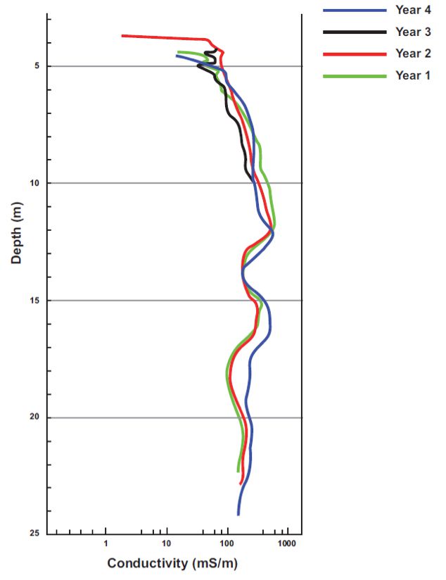
Downhole conductivity logging tools provide measured borehole interval conductivity readings. The borehole interval conductivity results can be correlated and interpreted alongside the observed geological borehole information. Downhole conductivity provides quantitative measurements of conductivity (mS/m) or resistivity (Ω.m), with measurements relating to changes in porosity, clay content and water quality.
Downhole Conductivity probes are frequency-domain electromagnetic (FDEM) instruments with a continuous sinusoidal transmitter waveform. In the frequency-domain, the secondary magnetic field has components both in-phase and out-of-phase with the primary magnetic field of the transmitter. Borehole conductivity probes typically measure only the out-of-phase component, and the instrument parameters (Transmitter-Receiver spacing, frequency and geometry) are chosen so that the measured response satisfies the so-called Low Induction Number (LIN) approximation. Subject to the LIN approximation, the measured secondary magnetic field is linearly proportional to the conductivity of the material surrounding the borehole. Subject to suitable calibration, the measure data can therefore be transformed to conductivity (or resistivity). Commercially available probes perform this transformation automatically. An example of a downhole electricity curve can be viewed in Figure 1.
Find the right solution for your next geoscience project
Talk to our experienced consultants about your project requirements. We help you discover the right approach for understanding subsurface conditions.